Disclaimer!
This was truly a MASSIVE undertaking and quite possibly the most technically challenging project that I have ever been a part of. As such, I spent an extensive amount of time discussing component selection with experienced PCB design professionals and the theory behind the project with an expert in quantum mechanics simulation… all to do my (relatively) smaller software integration and hardware simulation in the pictured below.
Truthfully, I am posting this more for what I learned than contributed. For more about this project, please go to Matt Bowring’s (the quantum expert) website here: https://mattbowring.com.
For my sweeping simplifications, followed by my own professional takeaways, please keep reading!
The Mission
We built this machine to solve optimization problems by mimicking the behavior of spins in a magnetic material (like in the Ising model). Each spin can be “up” or “down” (represented as +1 or –1), and the goal is to find the lowest-energy arrangement of these spins.
At some level, it is very likely you have already had exposure to this kind of problem and phenomena through popular discussions on quantum mechanics. This is because our goal with this machine is actually to simulate a process called quantum annealing through the accessible parts and mechanics of a PCB rather than expensive optical Ising machines.
📸 Photos
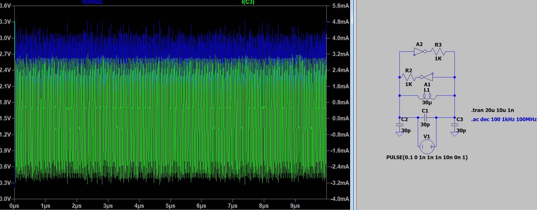 Each LC oscillator (an inductor + a capacitor) represents a spin. These oscillators naturally produce oscillating voltages (like sine waves).
The phase of an oscillator (where in the wave it is — like peak or trough) encodes the spin’s state:
Each LC oscillator (an inductor + a capacitor) represents a spin. These oscillators naturally produce oscillating voltages (like sine waves).
The phase of an oscillator (where in the wave it is — like peak or trough) encodes the spin’s state:
- One phase = spin up (+1)
- The opposite phase = spin down (–1)
 The oscillators are coupled through resistors, so they can influence each other — kind of like magnetic spins pulling each other into alignment (or misalignment) or the way that variables can influence each other in optimization problems.
The sign and strength of the coupling resistors are like the "J" values in the Ising model, which determine whether two spins want to align or not. Pictured above is the logic flow of our components. I went ahead and put it into a draw.io diagram to help with the coding portion later so we could actually encode our problems to be solved.
The oscillators are coupled through resistors, so they can influence each other — kind of like magnetic spins pulling each other into alignment (or misalignment) or the way that variables can influence each other in optimization problems.
The sign and strength of the coupling resistors are like the "J" values in the Ising model, which determine whether two spins want to align or not. Pictured above is the logic flow of our components. I went ahead and put it into a draw.io diagram to help with the coding portion later so we could actually encode our problems to be solved.
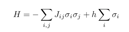 What problems can be solved? Anything that can be put into the Ising equation above. Depending on your love of "famous" equations, this may not seem impressive — but that actually includes: logistics & scheduling, vehicle routing, task allocation, portfolio optimization, neural network training (to a limited degree), circuit design and my favorite: qubit error correction (QEC) problems.
Optical versions of these machines have already been used for QEC but — who has that kind of equipment laying around? Again, our goal was to see if these systems could be placed cheaply on a board you or I could use and interface with a computer to do quantum-y stuff. Hopefully now you’re appropriately hyped.
 The board above uses an ESP32 to communicate with a MAX chip that acts as a FET array for the connections between oscillators. Those oscillators are paired variably via digipots, also receiving input from the ESP32. Lastly, to detect phase and frequency, we used a window detector. And to take in all the different data coming in from that detector I coded cascading shift registers to take the "shotgun" of signals and make them go along one path (also called parallel to serial). If you don't know anything about window detectors, I seriously recommend a quick Google — they solve a lot of key problems in signal processing for a fraction of the cost of an ADC with similar fidelity.
🎛️ Ising Coupling Interface
Ising Coupling Interface
Click a box to couple an A oscillator to a B oscillator. (Diagonal pairs disallowed)
1.0 kΩ
🎥 Demo Video
🔧 Features
- Spin-based problem solving
- Low-power analog computing
- Super Cool